A Trad![]() Boat
Special
Boat
Special
Building a Model Thames Barge
Part 1, Framing up Part 2 is now on site here
This page normally has a frame to the left. If you see it without, please click here
Introduction
|
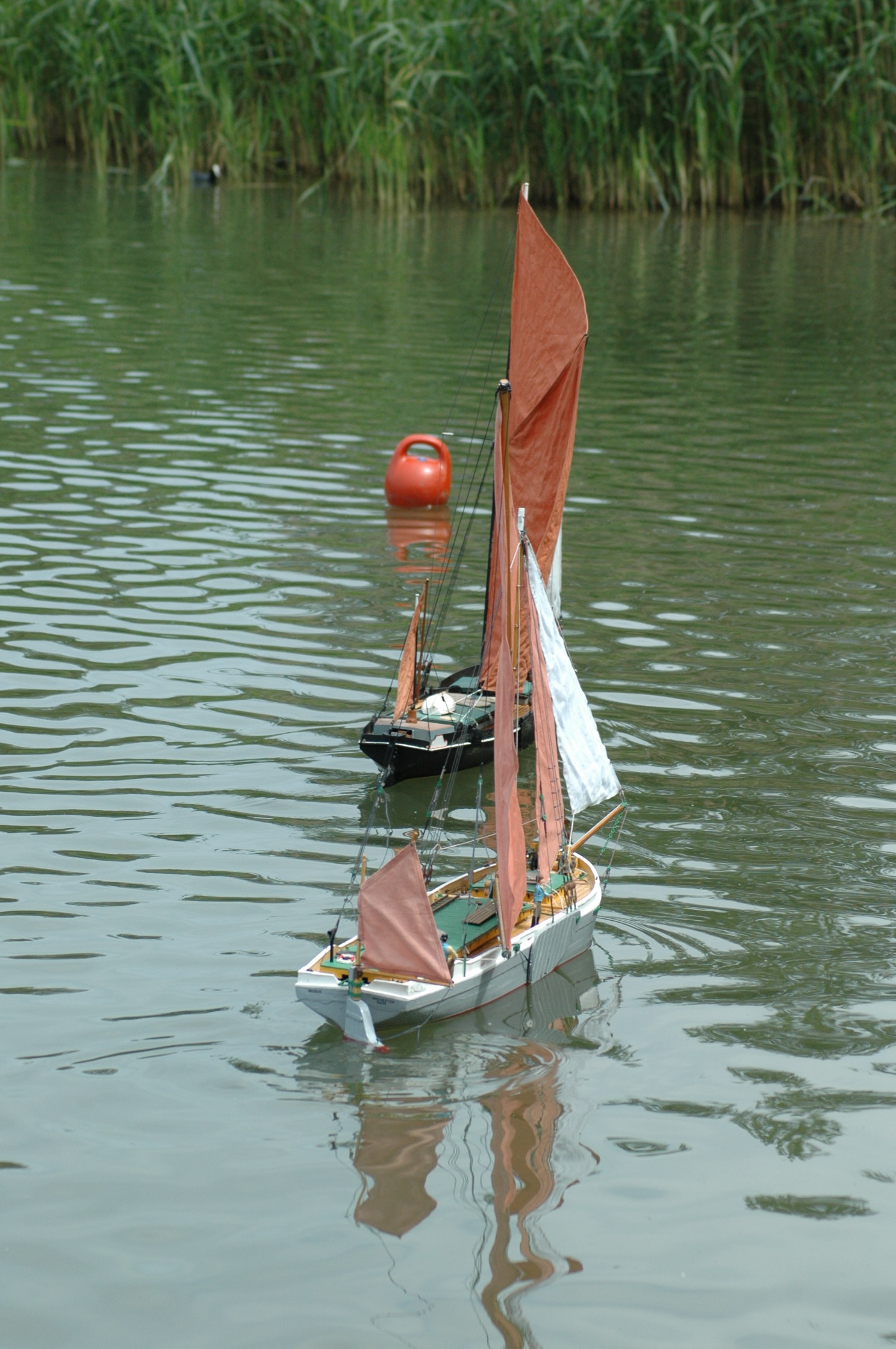
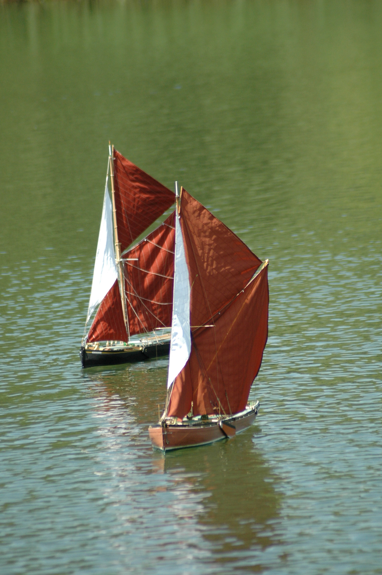
This is an on-going account of the construction of a model Thames Barge to the scale of ½inch=1ft, or 1:24. When finished the barge will be about 42" (1.1m) from stem to stern post. To that we have to add five or six inches for the rudder. So this is a big model. It fits into the Staysail category (that is without bowsprit) of the Association of Model Barge Owners (AMBO). ( Find more about AMBO here and press your Back button to return). Next year, hopefully, it will be racing in their barge match series. There are many ways of constructing a model barge. Some emphasise lightness for success in the racing season, others put in a lot of timber imitating full size practice as far as is practicable. Our barge falls about mid-way between these two options. Since this is our first project of the kind I have made notes about places where, with hindsight, we might have improved things .
|
Part One - Building board to frames
This part takes us to the point where the frames are completed
| Part One - Framing the Hull | Completing frames | Tools. Materials, Sources |
|
|
|
|
I chose to build James Piper (JP). Drawings by the late and much lamented James Taylor are available, already at the correct scale, that is at ½inch=1ft, or 1:24, and with much helpful detail. I chose to build from scratch - that is cutting out the frames and planking them, rather than obtaining a hull and completing it. GRP hulls for several barges are available if you prefer that route.
Several JPs have already been built, so there is always someone to advise. The design avoids the complications of rigging a bowsprit. The vessel has a straight keel for most of its length, and an attractive sheer. To obtain plans of James Piper or any other sailing barge, click on sources .
Preparing the Building Board
Mine is a piece of ½inch (12mm) blockboard, cut 2 feet wide by 4 feet long. This is a convenient size to buy because blockboard is sold in the metric equivalent of 8' x 4' sheets and many DIY stores stock this size. Ask them to cut the piece on their frame so that you get good parallel edges. Keep the spare piece for another model.
Draw a centre line
Assuming that the full size barge has a beam of about 20 feet, your scale beam at ½inch=1ft, is going to be about 10", or 5" either side of the centre line. I drew my centre line right along the length of the board, about 9" from one side. By drawing a line here instead of right down the middle of the board, you will be leaving a little extra width on one side which you can use as a work bench - useful if you don't have a lot of space.
Since this line is going to be the centre line of the boat, it must be straight.
Drawing the station lines
Now look at the plans; how many and how far apart are the station lines? (If you are not sure what station lines are, then click here and hit your Back button to return) These are going to be drawn on to the building board at right angles to the centre line. On my plans of James Piper the first station line - where the stem post comes - is numbered No 0 and the remainder are numbered 1 - 20 with a final station line for the transom labeled TR.
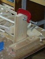
Transom jig
The station lines are two inches apart. JP is about 42 inches long excluding the rudder, so I started my No 0 station line (actually where the stem post will come) about three inches from the end of the board. Starting here leaves a little space into which my jig for holding the stem post fits nicely. It leaves a space at the other end for a jig to hold the transom. as you see here. At this stage it is clamped to the jig.
Draw the station lines to both edges of the board and number them. (I used short bits of masking tape and wrote the numbers on to them, but it would have been better to draw the numbers straight on to the board and sand them off later.)
Tips
Marking the intervals. I mark the two inch intervals along the centre line using a bradawl filed to a fine point rather than pencilling them on. When you come to draw the lines at right angles, you can pop the point of a fine pencil into the hole and bring the square up to it. In fact, I use tiny holes for as many marking points a possible, often using a very fine drill. Holes don't go away and they don't get rubbed out.
Make yourself comfortable. Take a two pieces of rounded hardwood beading and glue and pin them to both long edges of your building board. You will be spending a lot of time bending over this board and a smooth edge makes life a lot more comfortable. But don't do that until you have marked on the station lines.
|
Look at your plan (If you need to know more about frame drawings click here and then press your Back button to return). If your frame drawings are already at 1/2"=1ft, then you need only to photocopy them, once for each frame. (If the original drawings are, say, half that size, you will of course need to enlarge them first. Once done check with a rule that the scale marked on the plan has come up to the correct length.) Mid ship frames. You may find that there is no drawing for the mid-ship frames where, in a sailing barge, there is little or no change in the lines of the hull. For example, in JP, frames 13 14 15 and 16 are all the same - I simply repeated frame 13 four times. Alternatively you may decide to omit a number of identical mid-ship frames which will reduce the overall weight of the model and simply make a up a box when you come to planking the model. I decided to put all the frames in. So for JP you will need twenty-one photocopies. (OK I spoiled a few and made thirty copies in the end).
|
Tip: Do check that the business of photocopying has not distorted the drawings or elongated them.
Cutting out the frame drawings
Since only one side of the frame we want is drawn in the plans, we will need to fold the paper along the centre line, cut it out, and then unfold it to have a complete frame drawing.
I found that the key here is to fold each frame drawing exactly at the centre line, otherwise the result is a lopsided frame. I pricked a couple of holes in the centre line, one top and one bottom, and joined them up using a steel rule and an old bodkin in a tool holder which scores the paper lightly, and ensures that it does fold exactly at the centre.
Tip: Write the frame number on the drawing now, somewhere inside the lines where it won't get cut off. I wrote the frame numbers on every piece at every stage, having discovered that it was only too easy to wind up with unmarked frames and a guessing game.
Cut around the hull shape using a scalpel and a green cutting mat. Don't cut out the deck line yet.
Decks are not flat. Because they are designed to send water back over the side, they are higher in the centre than at the edges. This is round-up, familiar as camber on our roads. In some very simple craft the deck is flat and angled downward from the centre line, but in most vessels it takes a fair curve. Now you need to draw the deck round up on to the frame drawings.
The purists calculate the change in deck camber along the length of the vessel, so I am told, but this was beyond me, so I used the same round up throughout. I used a deck camber drawing kindly supplied by AMBO for "Westmorland", but there are other ways of calculating camber, some of them quite scientific.
To do the job, I made up a deck camber template. It has a centre line, is a little wider that the widest frame, and is cut from Plasticard, although any bit of reasonably stable cardboard will do.
Whilst the frame drawing is still folded, bring the template up to its centre line and adjust so that the outboard end of the template is exactly at the point where the frame drawing intersects with the deck line. Draw the round-up by running a pencil along the template, and then complete the cutting job. Don't unfold yet - see the next bit.
Reducing the frame drawings
By convention frame drawings are nearly always to the outside of the vessel. That is, to the outside of the planking or plating. The original JP is planked in three inch thick timber. Three inches at ½ inch scale = 1/8th of an inch all round, so the frame drawings are too wide at each side by that amount.
Whilst the frame drawing is still folded, draw a line inside the frame you have just cut out. You can do that, for example, by running a compass around the edge using its point as a guide. With your scalpel shave off that amount. Unfold, and you have the final shape of the frame.
(Confession, I didn't bother with this bit, so the whole thing is going to be ¼ inch too wide. Hopefully nobody will ever know.)
Putting frame drawings on to wood
I used two sheets of 6mm plywood for my frames. bought in a convenient size in a model shop. It was not to a waterproof standard so it is going to be coated with varnish, paint or epoxy to keep the water out. (There are much cheaper ways of getting materials, but having tried with ply from an old wardrobe which turned out to be as hard as iron, I gave up.)
Arrange all your drawings on the plywood in the most economical way. The girls are excellent at this being used to patterns. When you are satisfied, take the whole lot outside and spray each of the drawings, in turn, with Spraymount or similar, and stick them down flat. Let them dry.
Very Important: Spraymount is an adhesive in a pressure can. There are several makes, of which Spraymount is one. It MUST be used outside, or in a very well ventilated space. It smells strongly for a short time but has twin advantages. Because its used in graphics work it puts the drawing down flat, with none of the cockling that you get with "wetter" glues. And the drawing will peel off the wood without your having to wet it, when the job is done. A pressure can costs around £6 from WHS.
Now came the tricky bit. I practised on scrap plywood before cutting out the actual frames. Some modellers can do this successfully with a fret saw but I found that I couldn't, and so instead I used a small jigsaw purchased quite cheaply from a DIY shop, with a blade that produced a smooth cut, and running at its lowest speed.
I started by cutting around the edge of the paper frame template and then cutting out the centre of frame. To do that I drew a line around the inside of frame using a little T-shaped jig and a sharp pencil. In retrospect I would have made the deck beams a little deeper than I did, but in other ways the final shapes of the frame seemed about right.
The important thing here, is to ensure that those frames which are supposed to be identical are in fact identical. I have found that I had a bit of a wobble in most of them and so finally brought together those frames of the same shape, and cleaned them up so that they matched.
Once the inside of the frame has been cut out, the paper template can be peeled off. - but REMEMBER to put the frame number on to the wood otherwise the guessing game!
Tip. When you peel off the paper template you are clearly going to lose the drawing of the centre line. After some trial and error I found that the best way of ensuring that an accurate centre line could be drawn on the finished frame was to take a very fine drill and make a pin sized hole at the centre line both top and bottom. A fine line can now be drawn on the frame once the paper has being removed. I also made a very shallow saw cut in the top of frame at the centre line, which is very helpful later when it comes to lining up the frames.
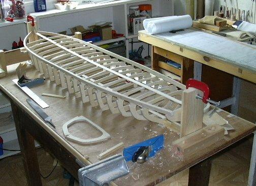
Each frame requires three notches. One at the bottom into which the keel will fit, and one at the deck line at each side into which a laminated in-whale will fit. When you come to place the frames - held in place with a little jig made up from scrap wood until the glue is dry - you can glue them to the keel and the in-whale, as you will see in the photograph below.
You might want to notch them also at the turn of the bilge to take a stringer but I did not do this relying instead on the overlap of the skin planking and an external "rubbing strip". Similarly you might want to erect the frames first and then add an in-whale - but I preferred to laminate the in-whale on the building board from the drawings on the plan.
Here the frames are in place glued to the keel. The inwhales are in their notches and the central part of the hull has been skinned
The Keel
The keel is made up from two square section lengths of hardwood with short lengths separating them. This makes up into a very rigid girder section and whilst not quite authentic is very strong. Things have now moved so please turn to Part 2
Part Two
Click here to go to Part 2.